Introduction
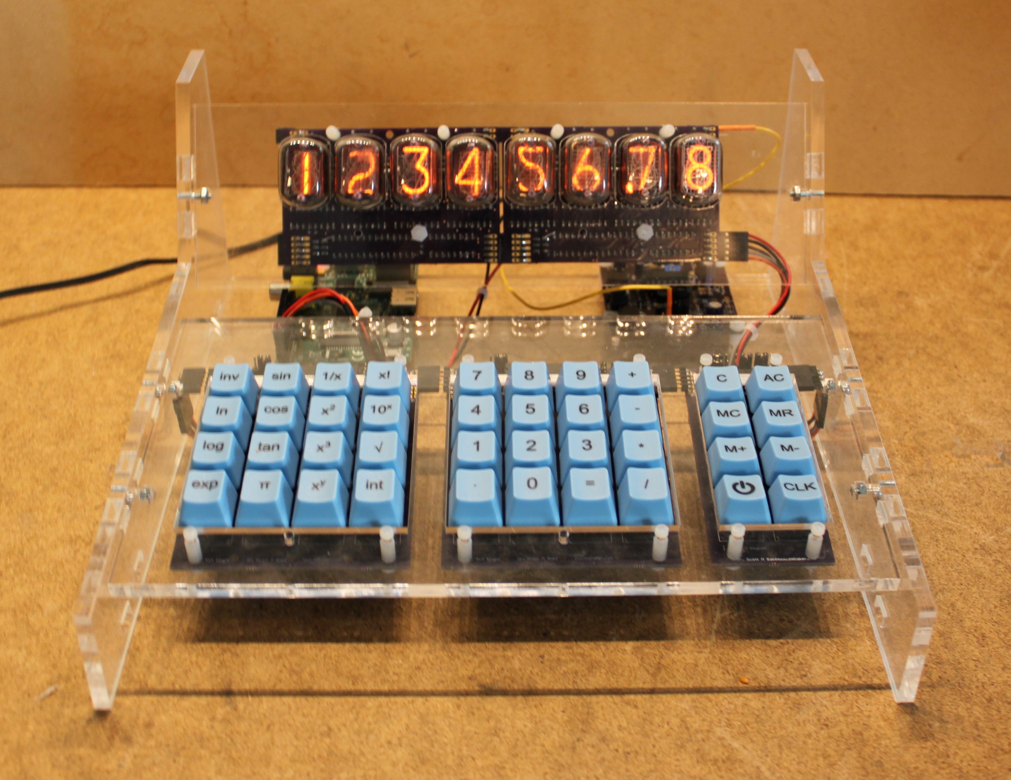
I’ve built several clocks. This is my first Calculator! This project has been launched on KickStarter — you can find it at https://www.kickstarter.com/projects/1555102420/nixie-tube-calculator. The Nixie Tube Calculator is a fusion of vintage and modern technology. It’s intended to serve as much as a piece of art as it is to serve as a functional device. The calculator is available in a variety of kit forms, depending on how much existing components you have on hand, as well as a fully assembled version.
Design Choices
I had many choices of which Nixie Tubes to use, and I chose the IN-12 for several reasons. I’ve used this particular tube in most of my other projects (the propeller clock, the propeller thermohygrometer, the raspberry pi clock, etc). First of all, they’re very cheap. You can pick them up on ebay for around a buck or two each plus shipping. Second, they use pin sockets. I really hate having to solder tubes direct to the board, like in the IN-14s.
The other key goals that influenced this project are hackability and modularity. To make the thing easily hackable, I went with the Raspberry Pi single-board computer. The Raspberry Pi is quite powerful for its cost (usually around $40 bucks), having the advantage that it can run plain ordinary Linux. This means we get a command-line environment that we can ‘ssh’ and ‘scp’ into, standard Linux tools for development, etc. The calculator software is written in Python, and interpreted language that is fairly easy for beginners to pick up and modify. The full source code will be made available. We only use two of the Pi’s IO pins to control the displays and poll the keyboard, leaving the vast majority of IO available for ‘hacking’.
Modularity is achieved by dividing the board into several different subassemblies. This allows you to mix-and-match. You could add more keypads or more displays to the calculator. The initial kit will have a total of 8 nixie tube digits and 40 keys, but I anticipate bringing out additional modules to add more digits and different-shaped keypads.
I2C is used as a bus to interconnect all modules, allowing new modules to easily be added.
Let’s take a look at the modules that make up a kit.
The Nixie Display Boards
The Nixie display modules have four tubes per each module. The basic kit includes two modules, for a total of 8 tubes.
Pin sockets are used on the board. These are available from digikey. They press in lightly and are then soldered in place. This leaves you with a nice board-mounted socket that the tube can be plugged into. Each tube has a dedicated K155D driver chip. The drivers are controlled by an I2C IO expander. A 16-bit IO expander can control all four driver chips. The drivers are sufficient to control the 0-9 numerals for the tubes, but not the decimal point. For the decimal point, there is an additional 8-bit I2C IO expander. That leaves four bits unused on the 8-bit IO expander, and I decided to put down footprints for controlling LED backlighting.
The Keypads
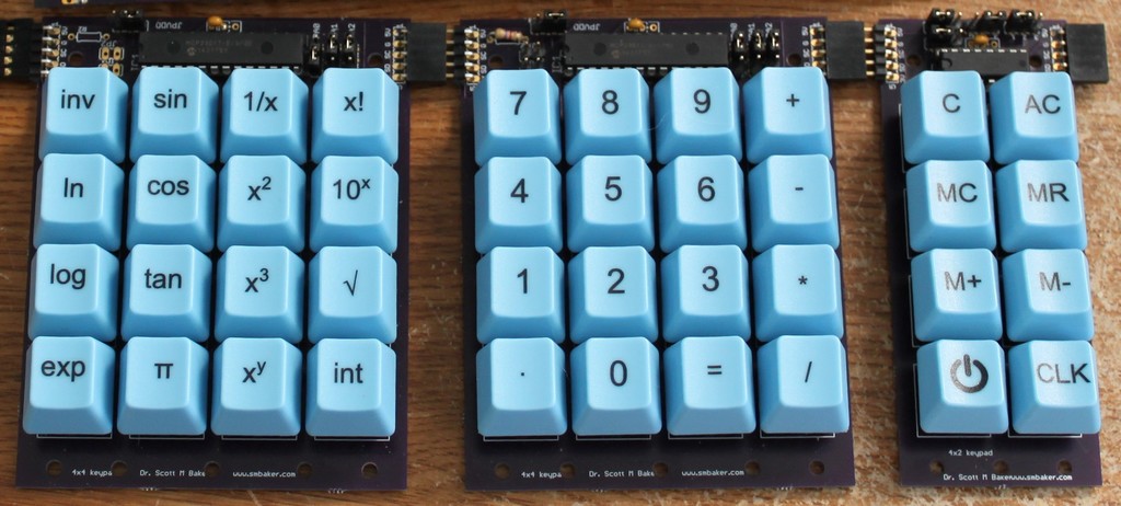
The Keypads use Cherry MX Blue key switches and custom printed keycaps.
Cherry MX Blue are quality key switches. If you’re a gamer, then you might already have a keyboard that uses these mechanical switches. They have an audible click and a good tactile feel. The keycaps can easily be removed and replaced. There are numerous places on the web that make custom keycaps at an affordable price, if the set of functions I’ve chosen for the keyboard isn’t to your liking.
Power Supply
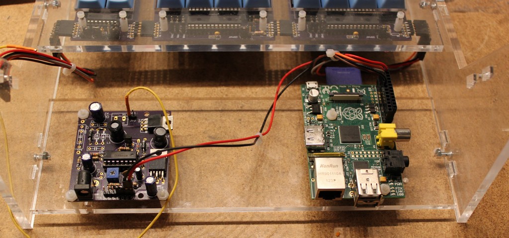
The power supply board is responsible for both 5V for the Pi and high voltage for the tubes.
Pictured above on the left is the power supply. There’s a barrel jack that allows you to plug in a standard wall wart (12V 1A is recommended). The power supply board is two supplies in one. If you look closely, you’ll see a 5-pin regulator. That’s a 5V switching regulator, and serves as an efficient means to convert the 12V down to 5V to power our Pi. The big socketed chip is a TL494 which forms the basis of the high voltage power supply. It uses a mosfet (the three-pin TO-220 device on the board) to drive a standard inductive boost converter.
Building the Kit
The entire kit is designed using through-hole components. While I’m familiar with using SMD and you might notice SMD parts in some of my other projects, the typical builder may not be. For that reason, I kept it simple. I do recommend you have a decent quality temperature controller soldering iron with a small tip. The $90 Hakko that you can find on Amazon is a good candidate. I also recommend using the finest solder that you can get your hands on. Those are my tips for successful soldering of through-hole components.
The kit will feature full step-by-step build instructions, but the basics are pretty simple — you start with the smallest components (IC sockets) first and then build up toward the taller stuff (inductors, capcitors, etc). I plan on putting together a video that shows a kit being constructed step-by-step.
The PC-Boards
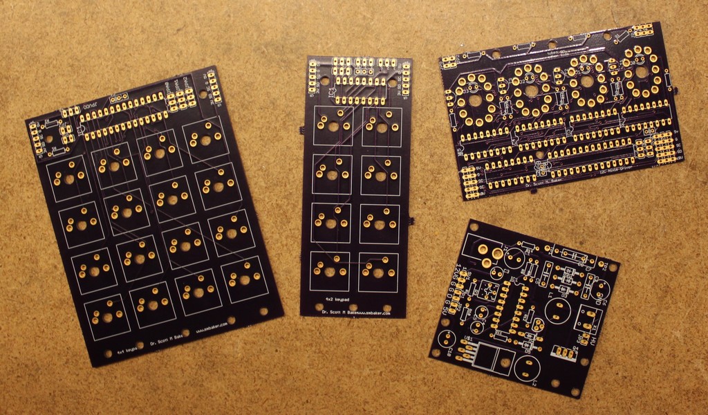
The PC-Boards used in the prototype were fabricated at OSH Park. I’ll probably try to come up with something a little bit more affordable for mass production (OSH Park’s pricing is optimized for providing a quantity of 3), but I’ll strive to have the same quality.
Above is pictured one sample of each board used to construct the prototype. The kits will include two 4×4 keypads and two 4-digit Nixie display boards.
The Case
The case is constructed from laser cut acrylic. For the prototype, Ponoko was used. You’ll probably notice that the back and bottom are partially open on the prototype. The real case will feature full back and bottom panels, to keep fingers from getting in there and messing with the electronics. The case is assembled using 4-40 hardware, which will be provided.
The Code
I’ve setup a github repository at https://github.com/sbelectronics/nixiecalc that will hold the code during the development process.
Some Videos
This first video is the initial cut of the ‘Kickstarter Video’, the one that appears at the top of the KickStarter page. It shows me talking about the calculator and demonstrating a few simple features:
The second video is my first prototype — let’s call this Nixie Calculator version 0.1 — roughly assembled on my desk. It’s a good way to see how the parts fit together and some of the design decisions that went into the kit:
This third video is me demonstrating Nixie Tube control using the Raspberry Pi and an I2C IO Expander, prototyped out on a solderless breadboard:


Are the keyboard PCB layouts available? This would be the perfect key layout for one of my projects. Looks like it uses a simple I2C bus extender for easy chaining.
Hi Scott! I’ve gone ahead and ordered a set of boards to make one of the calculators (I was a backer on the (alas) unsuccessful Kickstarter). Is there a BOM and any instructions on how to upload the code etc that’s available?
Cheers,
Nick
I don’t think I have a BOM up yet. The code is all python, and should mostly be a matter of copying it to the Raspberry Pi and running it. I’ll take a look through the documentation, and see I can think of anything that needs to be added.
Are the boards available for purchase? If not are the designs available for purchase so we can have boards made. This looks really cool.