Note: I use relatively small thumbnails in this guide so that we can fit a lot on screen. Each thumbnail is linked to a full-size image, so if you need a bigger look at something, just click the picture.
Part I: Fuel Injecting
Step #1: Fuel Tank modifications
A fuel injected setup is going to require two connections to the fuel tank. The first supplies fuel to the pump (much like a carbureted setup) and the returns fuel to the tank. Fuel injection regulators traditionally use a bypass design. The pump puts out an excess of flow and pressure and the regulator allows this excess to return to the tank, maintaining the preset pressure. Most sandrail tanks only have a single bung. You’re going to need to add a second for the return:
Above you can see the two bungs on the bottom of the tank. Each one has a flip valve attached to it. Fuel source is on the left (driver’s side) and return is on the right (passenger’s side). Flip valves came from grainger; I could never find a decent 1/4 valve at any of the auto-parts store.
NOTE: Don’t weld on the tank yourself unless it is a new unused tank. Even if it is supposedly unused, I’d make damn sure of it if I was you. Used fuel tanks can and will explode if welded on even if they appear to be empty. I had to shop around, most welding shops wouldn’t even consider working on it. Eventually found a local motorcycle shop that had the know-how and willingness to mod the tank.
Step #2: The fuel pump
Unfortunately, I can’t quite snip a good picture of this. I used a MSD high-pressure fuel pump and a summit screw-on canister filter.
Step #3: End-Castings
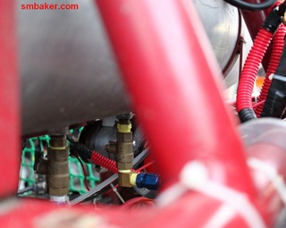
We’re going to need a place to mount our fuel injects on the intake. There’s several ways to do this including modifying stock end castings yourself. In my opinion, it’s far far simpler to just purchase the pre-made CB-Performance end castings. They cost $118.95 for a pair of them. Part number 7360. You’ll probably also want the fuel rails ($61.95/pair) and the associated hardware and clips. Here are pictures of the left and right end castings with injectors installed.
Step #4: Fuel injectors
I used Ford fuel injectors. Got em off ebay.
Step #5: Fuel Rails
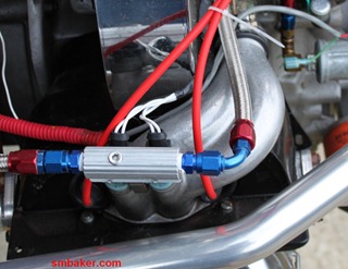
As discussed in the step on end-casings, it’s usually best to just buy the pre-made CB Performance fuel rails, clips, etc. I did have a friend who purchased fuel rail stock himself, cut it to size, drilled and tapped it. That sounds like an awful lot of work. Make sure to also get the clips to hold the rail to the injectors as a blow-off would be inconvenient and dangerous.
Step #5: Fuel Hoses
I used AN-Style hoses and AN-style fittings from summit. I believe they were “russel” brand hoses and fittings. AN fittings are the way to go because they’re easy to use, durable, and reliable. You can see them throughout the build. You make the hoses yourself by buying a coil of braided hose. An aluminum collar is threaded around the outside of the hose and then the fitting itself is threaded around the inside of the collar. It might sound complicated but it’s fairly obvious once you have the fitting in your hand. A desk vice is handy for clamping the hose in place while you tighten the fitting.
You need several hoses:
- Fuel tank to filter
- Filter to pump
- Pump to fuel rail #1
- Fuel rail #1 to fuel rail #2
- Fuel rail #2 to regulator
- Regulator bypass to fuel tank
Step #6: Fuel Regulator
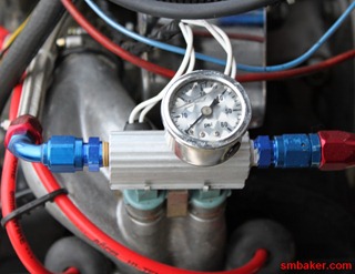
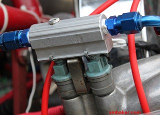
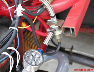
The fuel regulator we’re going to use is a bypass-style regulator. Fuel enters through the side and is returned out the top.
Note that this is the one place where I was unable to use AN fittings because the regulator came with barbs instead of threaded fittings. I’m not really happy about this and would much rather not have to use a traditional hose clamp. The small vacuum line attached to the bottom of the regulator is used to supply vacuum so that the regulator can adjust pressure to compensate for the amount of boost that the turbo is putting out.
Congratulations, at this point we have completed the fuel system. Now let’s move onto the air induction system.
Step #7: Center Casing
CB-Performance supplied us with the two end casings, but it’s up to us to find or fabricate a center casing. The center casing or “Y-Pipe” connects the two end casings to your intake manifold. To do it right, you could get someone to weld together some tubing for you.
I’m not going to do it right…. I’m going to to it cheap. I used a center casing off of a weber progressive carb kit. It’s the same technique that I used for the manx draw-through build. The top of this center section is intended to mate with a weber DFEV carb. I made an adapter to convert from the weber bolt pattern to the bolt pattern of the throttle body.
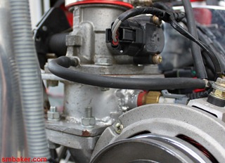
The intake manifold is where we need to mount our first sensor, the intake air temperature sensor. I purchased a steel bung for this sensor from diyautotune.com and welded the steel bung to my manifold adapter. The sensor threads right in. It’s a little hard to see in the picture below. The sensor is on the right of the manifold, partly hidden by the alternator.
Step #8: Throttle body
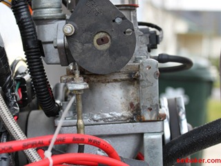
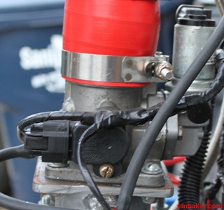
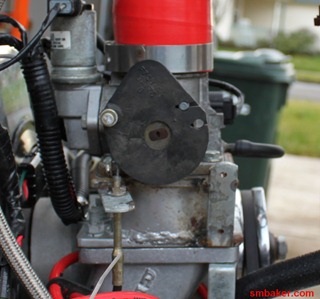
The throttle body that I used is a ford throttle body. It has several advantages: it’s relative small and appropriately sized for the VW aircooled engine. It case built-in TPS sensor and a built-in idle valve. It also has a couple of disadvantages: the idle solenoid doesn’t work all that well with the megasquirt and and throttle cable didn’t quite come out in the most ideal configuration for me.
The black plastic sensor in the above left picture is the throttle position sensor. It’ll tell the megasquirt how far open the throttle is. The metal can coming out the back of the throttle body is the idle valve. The megasquirt uses it to supply the engine with additional air when it is cold and to (attempt to) regulate idle speed.
I don’t quite recall where the throttle cable came from. I think it was a cruise-control cable that was leftover from the mazda rotary build. It’s a short cable that runs to an adapter that couples it to a traditional morse cable.
Step #9: Coolant Sensor
The next step is to install the coolant sensor. Wait…. what??? It’s a VW. We don’t have coolant.
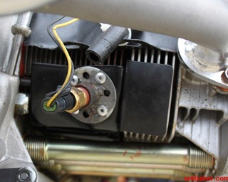
Well, we’ll have to do the next best thing. The megasquirt needs to know whether the engine is “cold” or “warm”. It uses this information for a variety of purposes including control of the idle valve. It doesn’t have to be precise; it just needs to be a general indicator. So what we’ll do is to attach our coolant sensor to the cooling tin on one of the cylinders.
As you can see I built a small round plate, welded a bung to it, and then rivited the assembly to the cooling tin. When the engine gets hot, the cooling sensor will get hot. Everything works as intended.
Step #10: Oxygen sensor
We’re getting a little bit ahead of ourselves here since we haven’t even talked about the exhaust or the turbo yet. Suffice it to say that you need an O2 sensor. Wide-band sensors are much better than narrow-band sensors, but also cost a heck of a lot more. I absolutely recommend going with a wide-band, because it’s going to be a paint to tune your engine without one.
I fabricated up a temporary non-turbo exhaust and welded the O2 bung to it. No pictures of this as I’ve already discarded the temporary exhaust.
Step #11: Ignition
The megasquirt needs to know your ignition timing, because it uses this information to calculate how to fire the injectors. There’s many ways to do this and the megasquirt manual will tell you all of the various options. You can also have the megasquirt control your ignition, advancing or retarding spark according to boost.
I chose to keep it fairly simple. I already had an MSD ignition box that was connected to my distributor. I used the tach output of the ignition as the signal to the megasquirt. The MSD tach output is already a nice clean signal, so this is good. It’s a pretty simple way to get the system up and working.
Step #12: Fabricate and install megasquirt ECU
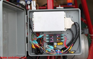
This step is a big one. You buy a megasquirt kit (mine was from diyautotune) and solder it together. You buy a wiring harness and wire your sensors, injectors, fuel pump, relays, etc. I’m not going to describe all of the because the megasquirt manual does a lot better job of it than I could. The megasquirt ECU itself is neither water nor sand proof so I chose to mount mine inside of a plastic irrigation timer box:
As you can see above inside this box is a fuse panel that holds my various ignition-on fuses. These supply injector power, etc. There’s also several relays that are hidden behind the plastic panel in the back of the irrigation timer box.
The manifold pressure sensor is built into the megasquirt and connects via a vacuum hose to the throttle body.
Step #13: Try it out
At this point we don’t have the turbo, but we have everything else that we need to get the motor working. We have the fuel system (tank, pump, injectors, regulator). We have the air intake system (End casings, center-section manifold, throttle body). We have our sensors (coolant, intake air temp, throttle position, manifold pressure).
My megasquirt fired up with almost no tuning required. I used a suggested mapping from someone else, probably one of the people on either the megasquirt or shoptalk forums.
Part II: Turbocharging!
to be continued….
