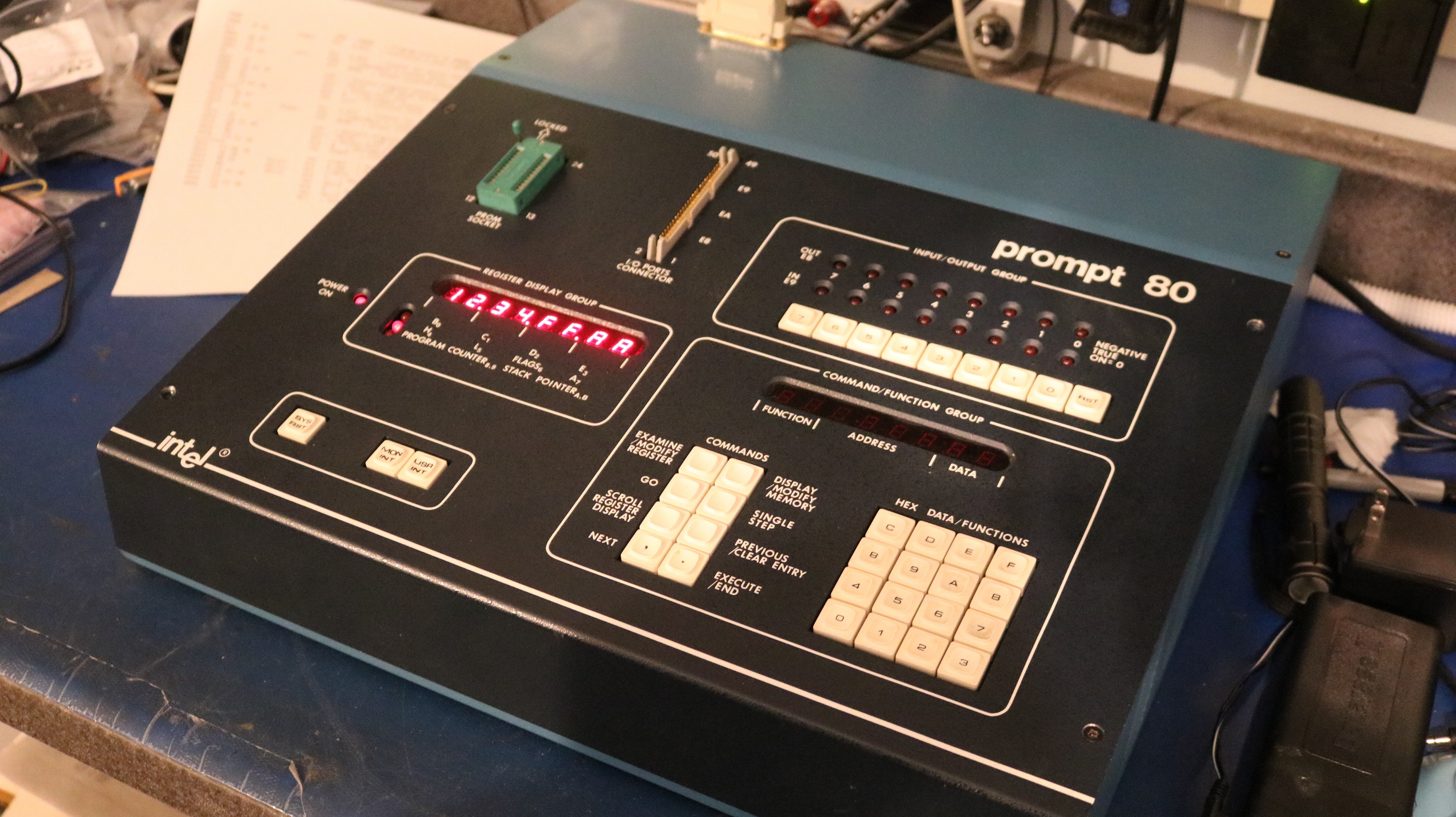
In this blog post, I bought a Prompt 80, without CPU board, from eBay and I get it up and running.
Then I put the Forth programming language in ROM and add a speech synthesizer.
What was the Prompt 80 ?
I couldn’t find the manual for the Prompt 80 anywhere, but I can paraphrase from the Prompt 48 manual and do a few string substitutions to figure out what the product descrption might have looked like:
Prompt 80 is a tool to aid you in learning MCS-80 programming and in writing, debugging, and testing the programs you write. There is enough information here to get you started, whether or not you have ever written a program before.
Prompt 80 is a machine-language computer; making it support assembly-language programming would have considerably raised its cost. Even so, it is general purpose, and can be used to perform a variety of tasks, among which are the control of TILcompatible devices and the programming of (E)PROMs. The pins of the onboard 8255 peripheral interface can be directly interfaced to your prototype via the I/O PORT CONNECTOR.
If anyone does have a Prompt 80 manual, please do let me know!
Basically, it’s what many peope would call a “trainer”. Lots of trainers existed in the day to give people access to a microproccessor so they could type in and execute a program without having to design the hardware. It let you get up and running with a CPU, in this case the 8080 CPU, quickly. This could be as both an educational tool for new programmers as well as a marketing tool for CPU companies, to rapidly get their products into the hands of potential developers and customers.
Adding a CPU board
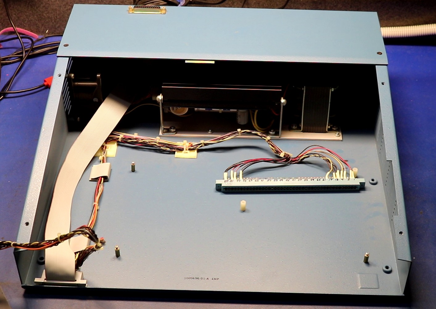
As received from eBay there was no CPU:
I knew this as the seller had taken excellent pictures for the listing, and even disclosed to me that he had placed the CPU board up in a separate listing:
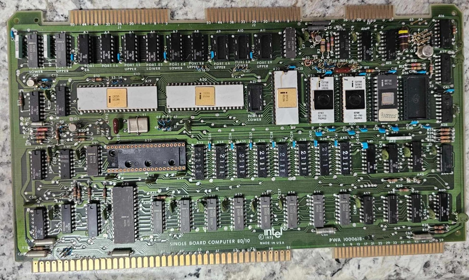
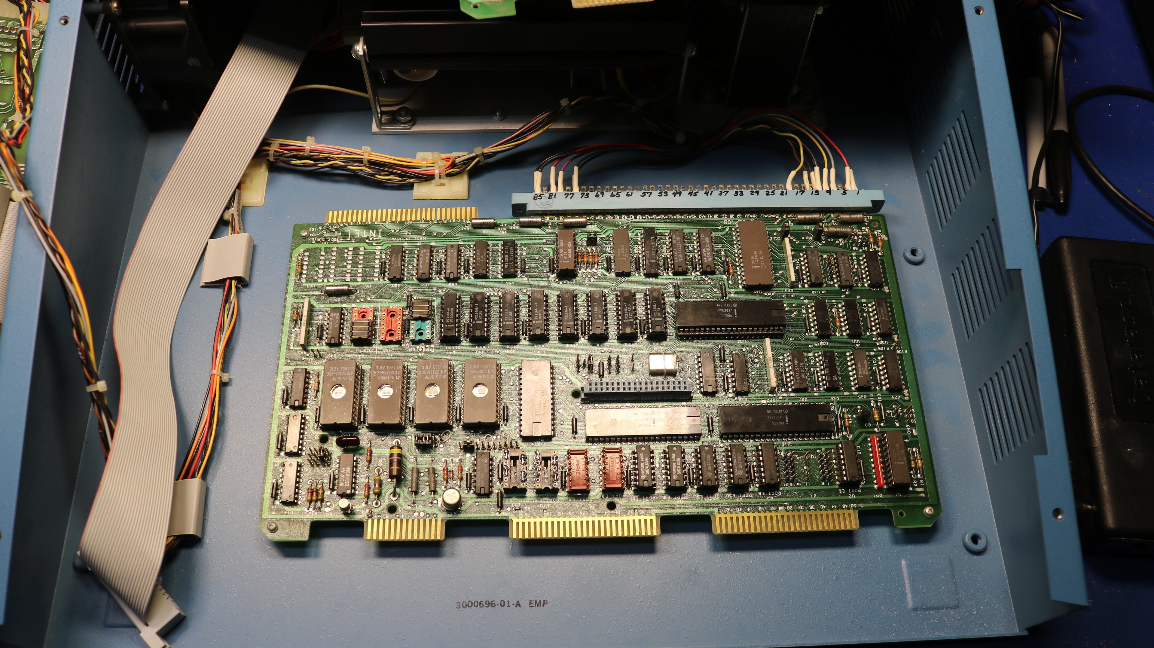
The original board was an 80/10 had the desirable and expensive white ceramic ICs on it, and unfortunately, I decided it was outside of my price range to reunite that board with this computer. You can see above two white ceramic 8255 ICs, a white ceramic UART, and two white ceramic 2708 EPROMs. I ended up purchasing a slightly newer 80/10A for about $50 bucks and installed that instead:
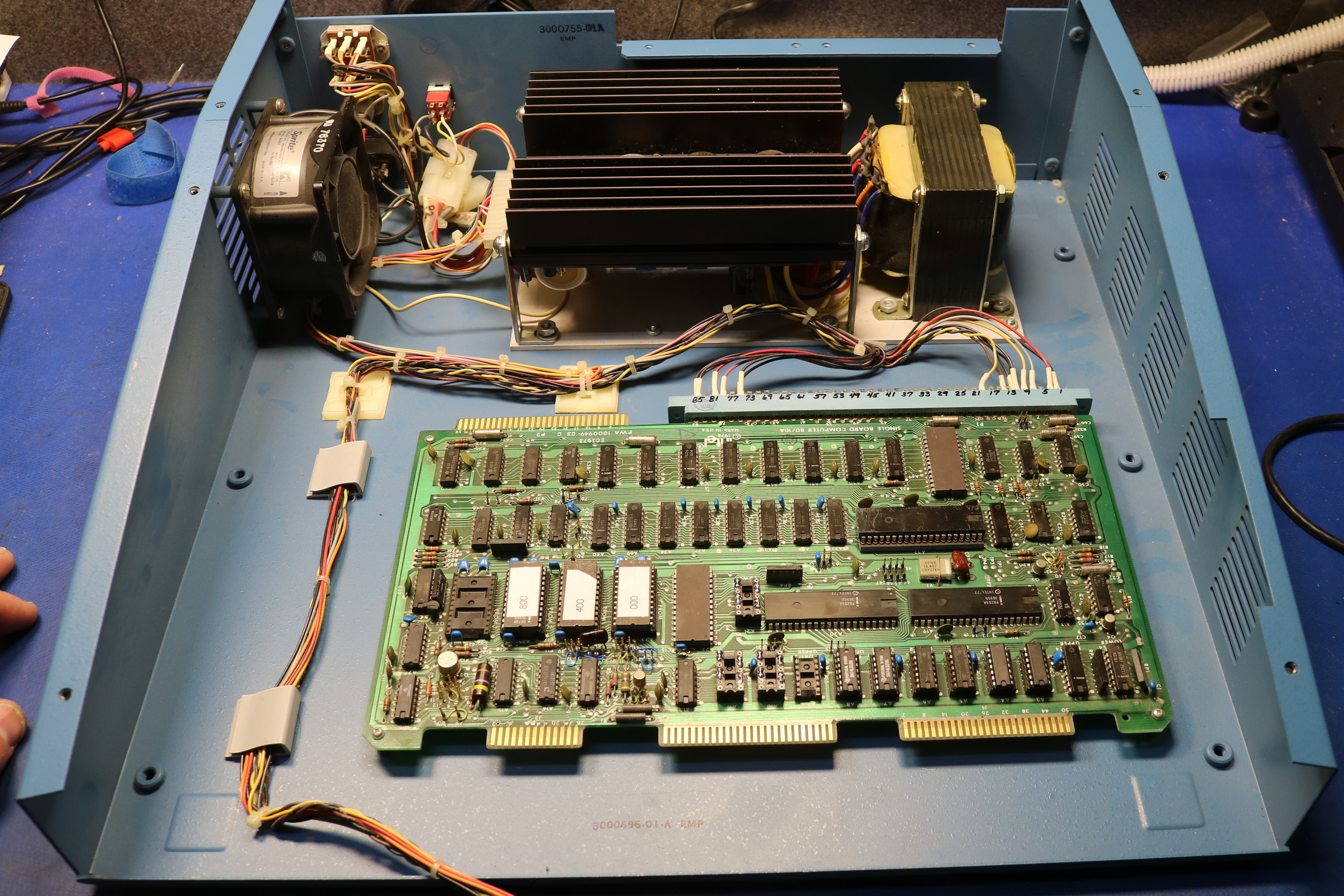
Later I upgraded it to an 80/10B. The 80/10B has a few advantages over the 80/10A:
- Up to 4KB of RAM instead of 1KB
- One multimodule slot, allowing a small module to be piggybacked on top of the board
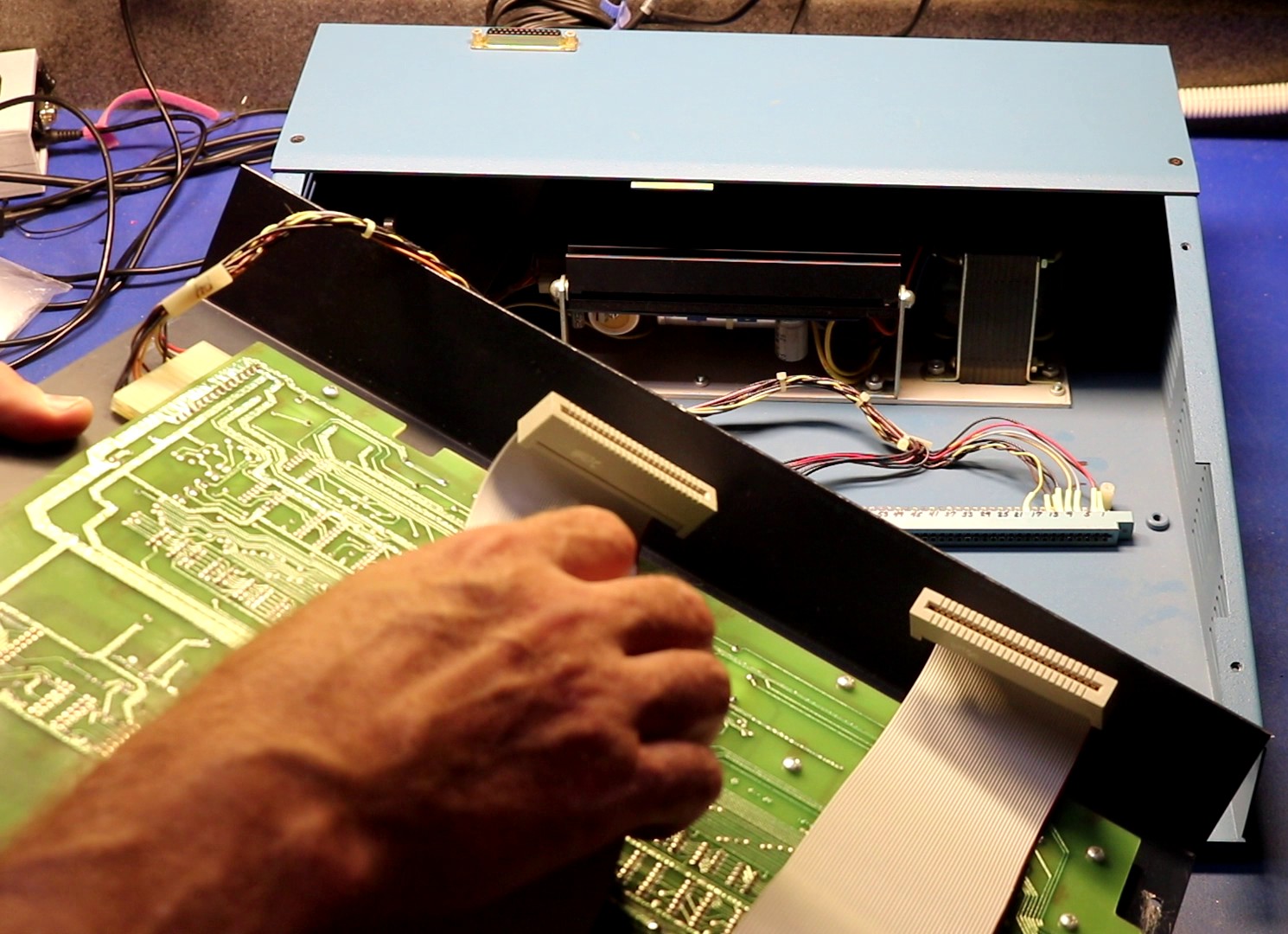
The front panel connects via a couple cables to the large edge connectors on the CPU board:
Fixing the power supply
Before powering up the computer, I checked the rails on the power supply. Always do that with very old computers. In this case, my multimeter showed only 0.8 volts on the 5V rail. It wasn’t going to work like that. I removed the power supply:
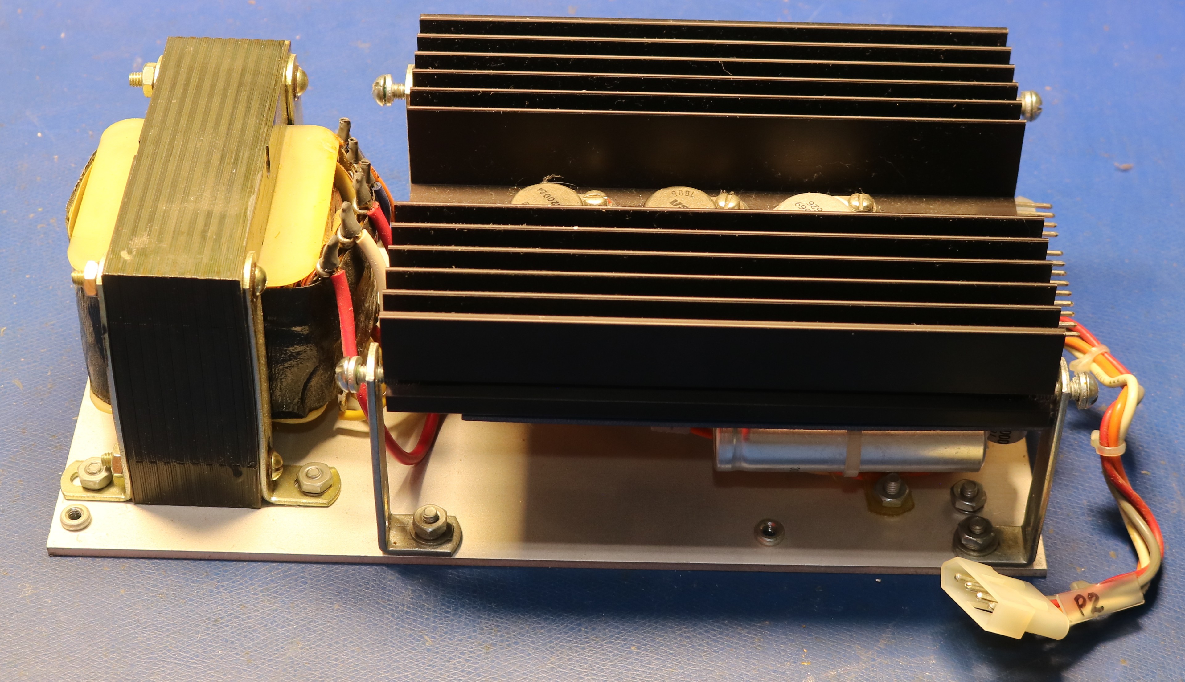
The power supply is a nice self-contained module, a linear design, with a beefy transformer. There are three TO-3 devices mounted to the heatsink:
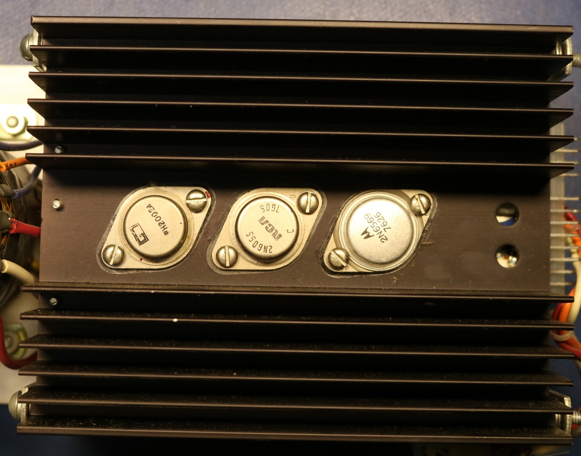
The three TO-3 devices are soldered to the pcobard, which makes the thing a little hard to disassemble. Here’s a view of the pcboard from the other side:
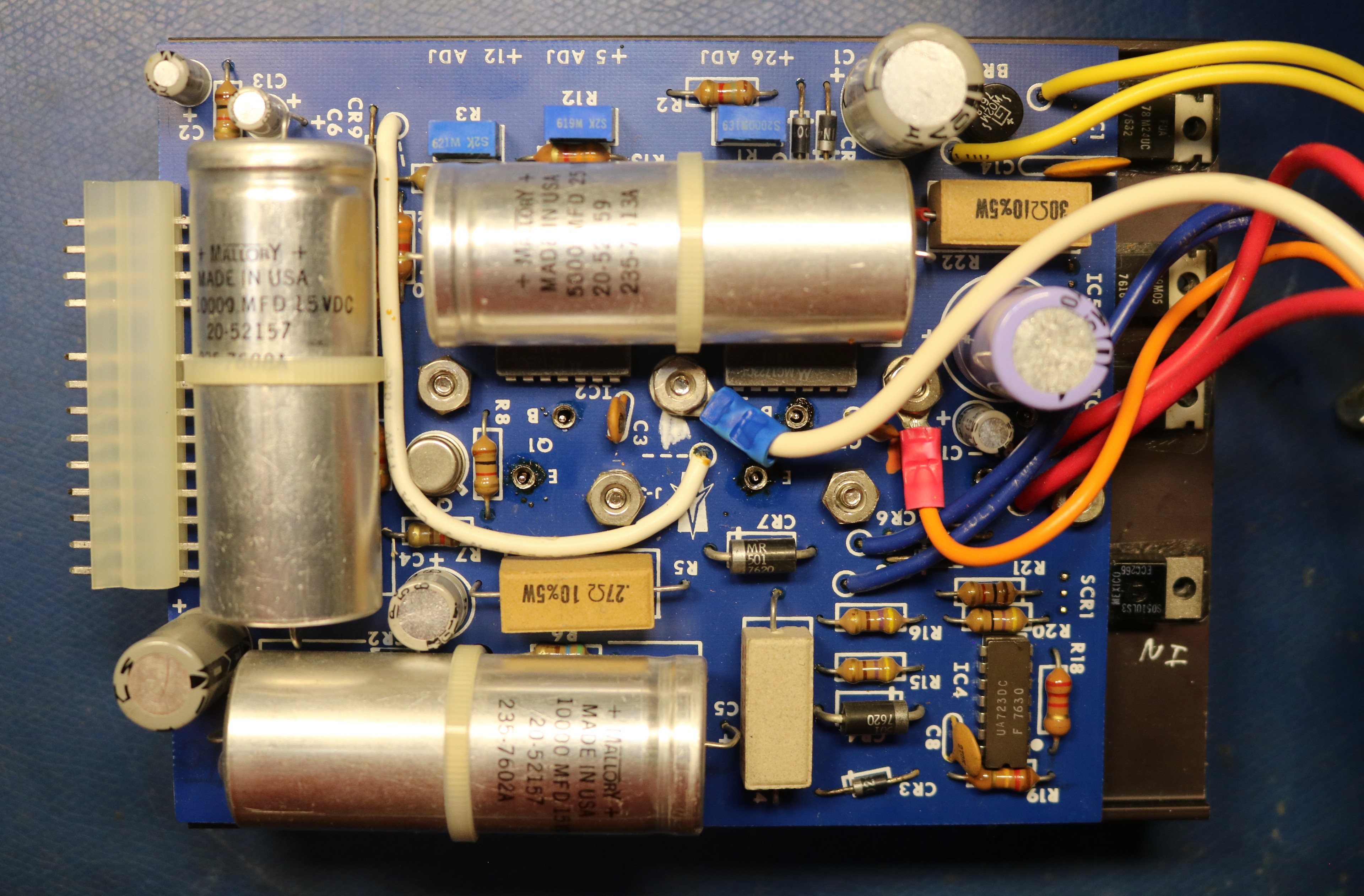
We can see several large filter capacitors — two are 10000uF/15V, and the third is 5ooouF/25V. There are also a plethora of smaller capacitors. I pulled every single capacitor and bench tested them all. Surprising the three large filter capacitors tested good. Several of the small capacitors tested bad. I replaced all the small capacitors.
After rhe recapping, the power supply started working fine, and I got my 5V on the 5V rail. I reassembled everything.
Trying out an assembly language program
I used Anthropic Claude to write myself a “cylon LED” program to make the LEDs attached to the parallel port light up back and forth:
;; Note: ORG 3000H assumes 80/10B with 4KB of RAM
;; If using 80/10, try adusting to 3D00H instead.
;;
3000                          .ORG   3000H   ; Program starts at 0000H
3000   3E 01        START:    MVI   A,01H    ; Initialize A with rightmost bit
3002   06 07                  MVI   B,07H    ; Counter for shifts left
3004   2F           LEFT:     CMA            ; Complement A (invert bits)
3005   D3 E8                  OUT   0E8H     ; Output inverted pattern to port E8
3007   2F                     CMA            ; Restore original pattern
3008   CD 21 30               CALL   DELAY   ; Add delay between shifts
300B   07                     RLC            ; Rotate bits left
300C   05                     DCR   B        ; Decrement counter
300D   C2 04 30               JNZ   LEFT     ; Continue until leftmost position
3010   06 07                  MVI   B,07H    ; Counter for shifts right
3012   2F           RIGHT:    CMA            ; Complement A (invert bits)
3013   D3 E8                  OUT   0E8H     ; Output inverted pattern to port E8
3015   2F                     CMA            ; Restore original pattern
3016   CD 21 30               CALL   DELAY   ; Add delay between shifts
3019   0F                     RRC            ; Rotate bits right
301A   05                     DCR   B        ; Decrement counter
301B   C2 12 30               JNZ   RIGHT    ; Continue until rightmost position
301E   C3 00 30               JMP   START    ; Repeat forever
3021   16 20        DELAY:    MVI   D,20H    ; Outer loop counter
3023   0E FF        DELY1:    MVI   C,0FFH   ; Inner loop counter
3025   0D           DELY2:    DCR   C        ; Decrement inner counter
3026   C2 25 30               JNZ   DELY2    ; Continue inner loop
3029   15                     DCR   D        ; Decrement outer counter
302A   C2 23 30               JNZ   DELY1    ; Continue outer loop
302D   C9                     RET   ; Return from delay
It might not be the best code in the world, but Claude’s program worked, and you can see it in action in the demo.
Reading and writing an EPROM
To read an EPROM from the onboard ZIF socket, use the following combination
- 4 (function 4)
- start address in RAM
- end address in RAM
- address in ROM
For example, the key sequence “4 3 D 0 0 , 3 D F F , 0 0 0 0 .” will read 256 bytes from offset 0000 in the EPROM to RAM from 3D00 to 3E00.
To program the EPROM, use a similar sequence:
- 2 (function 2)
- start address in RAM
- stop address in RAM (must be multiple of 16 bytes)
- address in ROM
For example, the key sequence “2 3 D 0 0 , 3 D 3 F , 0 0 0 0 .” will write 64 bytes from offset 3d00 to offset 0000 in EPROM.
Adding FORTH
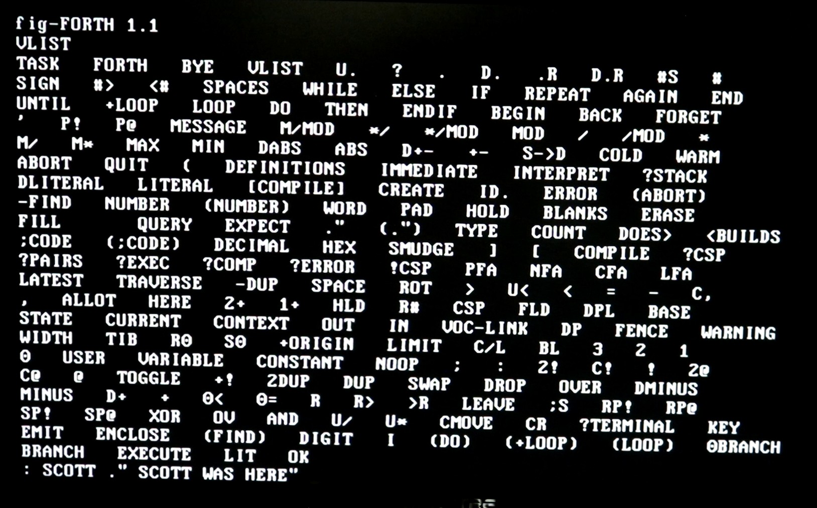
Forth is my favorite vintage programming language. I started with 8080 fig Forth 1.1. Unfortunately, this is not directly “rommable” and will try to self-modify itself in many locations. I followed the guide written by Ted Croal in the article “8080 fig-FORTH in ROM” in Forth Dimensions Volume IV Number 4, and I was able to make the fig-forth rommable following his instructions. Then I proceeded to delete everything I could to slim it down to fit into 5KB or less of ROM. This meant dumping forth words for disk io, screens, blocks, etc. We don’t have that stuff anyway.
5KB of fig-forth plus 3KB of monitor leads to 8KB total, which fit in four 2716 on the 80/10B board. Perfect.
You can find my hacked-down fig-forth source code in my github repo.
Having Forth on the Prompt-80 is fun as this gives us a high-level language we can program in via the serial port. It gives it a more “real computer” feel.
Speech Synthesis
The 80/10B includes a multimodule socket, so I installed my SP0256A-AL2 speech multimodule into that socket and wrote a couple short assembly programs to say “Scott Was Here” and “This is an Intel Prompt 80 Computer”. You can hear it talking in the demo. The speech programs are relatively short and are also checked into the github repository
Conclusion
In conclusion, the Prompt 80 is a really cool trainer. It’s bigger and heavier than most single board computer trainers of the days (and it’s actually a two-board trainer). The use of a multibus board as the CPU board allows you to easily swap different boards in — we could easily use an 8085 board or an 8086 board albeit with a rewritten monitor if we wanted to. Having two sets of LED displays with one dedicated to viewing registers is a nice touch.