If you’ve watched my recent video on the Nixie tube clock, you may have noticed that my clock didn’t have a power-on reset capability. It sat there locked up until someone flipped the reset switch.
I spent some time looking over the Internet and came up with two options for reset circuits:
Option 1: The MAX811
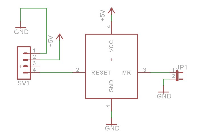
The MAX811 is what Maxim refers to as a microprocessor supervisory circuit. They watch the vCC signal and when it falls below a preset threshold, they will assert the reset signal for 140 milliseconds. You can buy the MAX811 in a variety of different thresholds. The ones I chose were the MAX811LEUS, which has a threshold of 4.63V, which seems appropriate for a 5V project like my RC2014. Since the MAX811 is designed to serve exactly this one purpose of voltage monitoring and asserting a reset, it does it quite well.
The !MR signal is for connection to an external reset button.
Option 2: An RC timer reset circuit
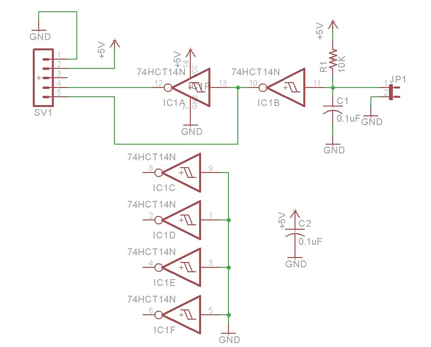
The RC Timer reset circuit uses a resistor and a capacitor to cause the reset signal to be asserted when power is applied. When power is disconnected, C1 will approach ground. As power is supplied, C1 will charge via R1. If the voltage on C1 is below the threshold necessary to be detected as a logical high by IC1B, then IC1B will output a high, which in turn causes IC1A to output a low. This asserts our reset.
As C1 charges, it will eventually be above the threshold necessary to be detected as a logical high. IC1B will output a low, and IC1A will invert that to a high. This drops our reset signal and allows the microprocessor to run.
Although I used a schmitt trigger inverter in this schematic, it should be possible to use a regular inverter, which the caveat that the reset signal might flop on and off wildly as C1 is charging (schmitt trigger has hysteresis which should prevent this from happening).
Note that the above schematic has both an R and a !R output, this is handy if you have circuits that are both reset low (like a Z80) and reset high.
Implementation
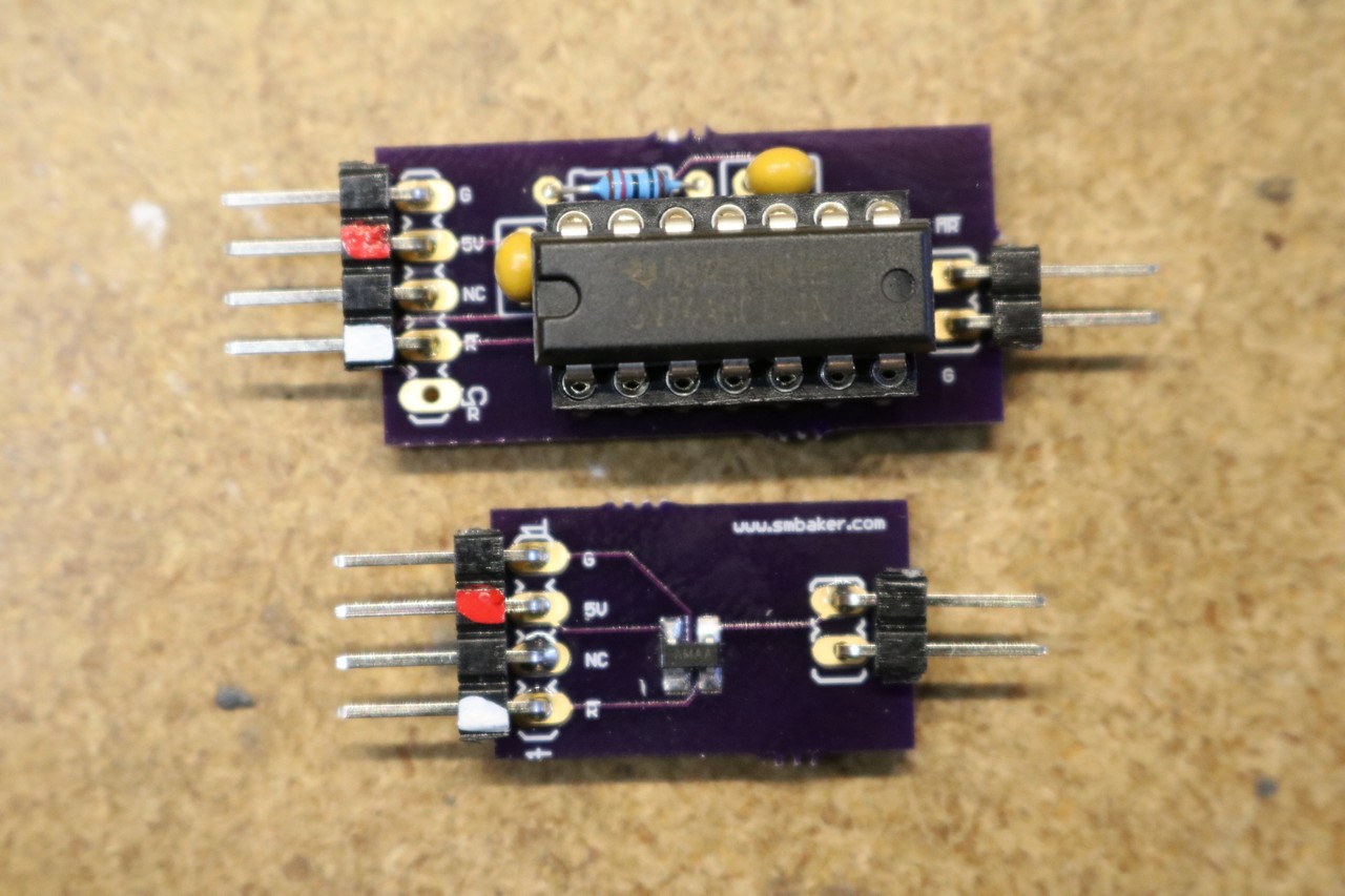
I constructed both of these circuits and they are shown below:
I tried out both of them in my RC2014 Nixie Tube Clock, and they both worked fine for power-on reset. I ended up going with the RC schmitt trigger version as it seemed more accurate to the period.
PC-Board availability
Circuit boards for both of the above are available on Osh Park:
Max-811 version:
RC-Timer version:


