While working on the DIY RF generator, I decided to experiment with some VCO modules that can be found on ebay. These are typically found on the listing “70-200MHz VCO RF Signal Source Voltage Controlled Oscillator Signal Generator”. My video blog entry where I put the module through its paces is below:
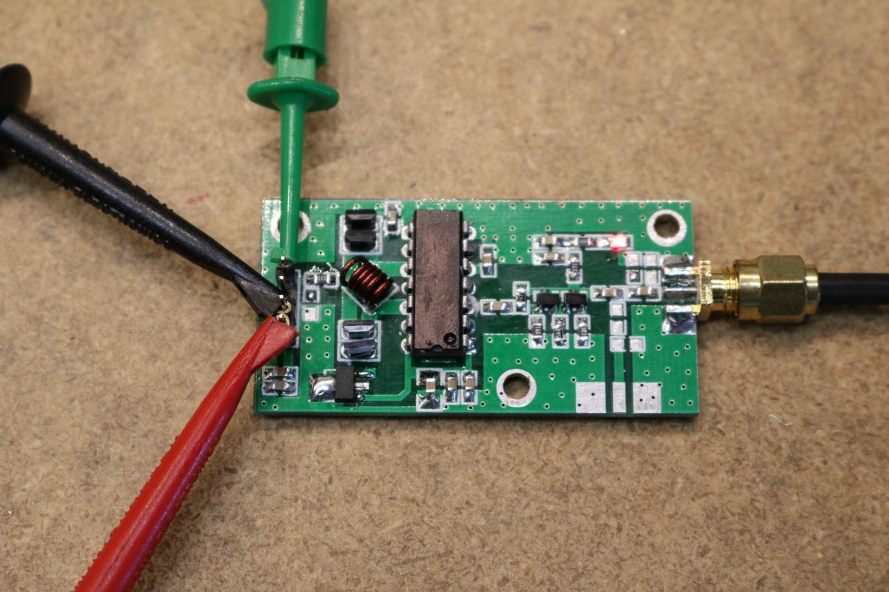
Here’s a high-resolution picture of the module:
The chip with the identification scraped off I’m pretty sure is a MC1648 voltage controlled oscillator. The summary is that the module appeared to work pretty well, and was a decent value for the ~ $20 that I paid for it.
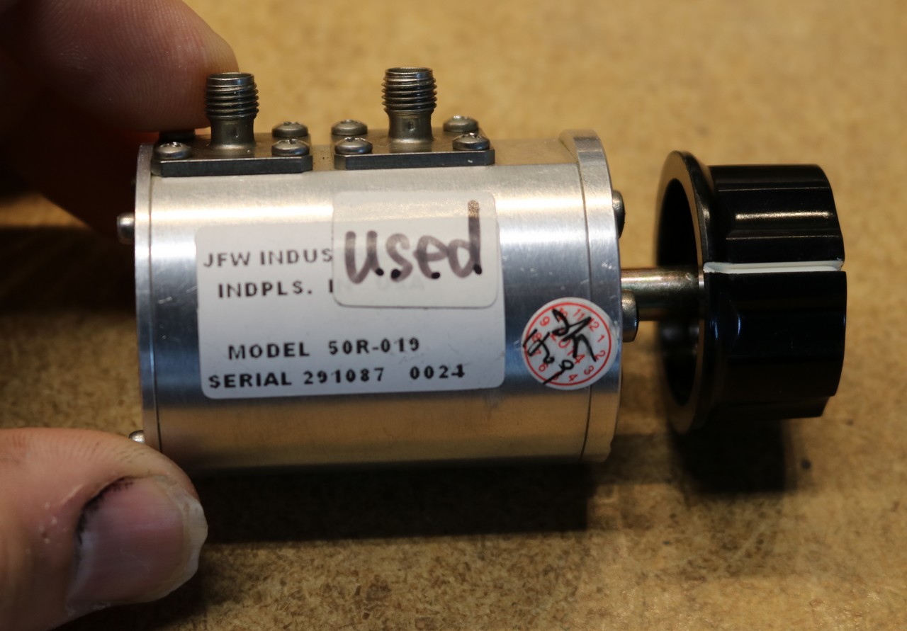
You could take one of these modules and make yourself a reasonably cheap benchtop 70-200 Mhz RF frequency generator. In the video, I also take a look at some other eBay finds, including a used RF stepped attenuator, a cheap BNC crimping tool, and some BNC and SMA connectors. I made my own BNC-to-SMA cable to attach the VCO module to the oscilloscope. Here’s a close-up of the stepped attenuator:
So what is a stepped attenuator? It’s kind of an alternative to a pot. Rather than have a continuously variable adjustment, you have a selector switch with a series of stops (in this case 10) that offer precise levels of attenuation, usually at decibel intervals. At each step of the selector switch, a resistor attenuator will be selected in. This provides both precision (high precision resistors are used) as well as proper impedance matching. These things can be really expensive, on the order of hundreds of dollars, and that’s why eBay is a good source.
The stepped attenuator I planned on using in my DIY RF signal generator, but it turned out to be a really tight fit. I ended up building a standalone attenuator instead — see that in a future blog post.


Hi, the distortion in the signal and the fluctuation of the level through the range seem like the problems Dave showed in one of its videos. This scope does not have a 50ohm input impedance and hence it should be properly terminated, the way you have terminated it to the frequency counter.
Here’s the video “EEVblog #652 – Oscilloscope & Function Generator Measurement Trap” if you haven’t seen it yet. Let me know if this was the case, I’m curious.